

簡述
前幾篇介紹了編碼器的工作原理及PID的基礎理論,接下來要將兩個結合在一起,並且去控制馬達到指定位置。
正文
在PID理論篇中有差分法的公式
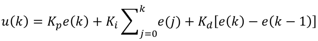
其中e(k)為

根據以上的公式將Set Point及Process Variable做相減,可以得e(k),而Set Point是目標的編碼器數值,Process Variable是目前編碼器數值
將e(k)的參數帶進去差分法的公式後就可以得到u(k)輸出了,u(k)的參數定義是馬達的電壓大小,所有的馬達控制都不太一樣,但是核心理念是差不多的。
一般有刷馬達是用電壓控制速度,而電壓是由放大電路所產生的,用arduino的板子來比喻的話,5v轉12v給馬達,而5v的解析度是255,因此設定255就是最大電壓輸出。
馬達的控制方式有很多種,因為有很多不同種類的馬達,但是不管是哪一種馬達,最終的核心就是會有控制馬達的速度,這個控制並不是閉迴路,而是開迴路控制,就算控制量設定50%,但會根據電壓或電流的狀態而不一樣,因此才需要閉迴路來回授控制位置或速度
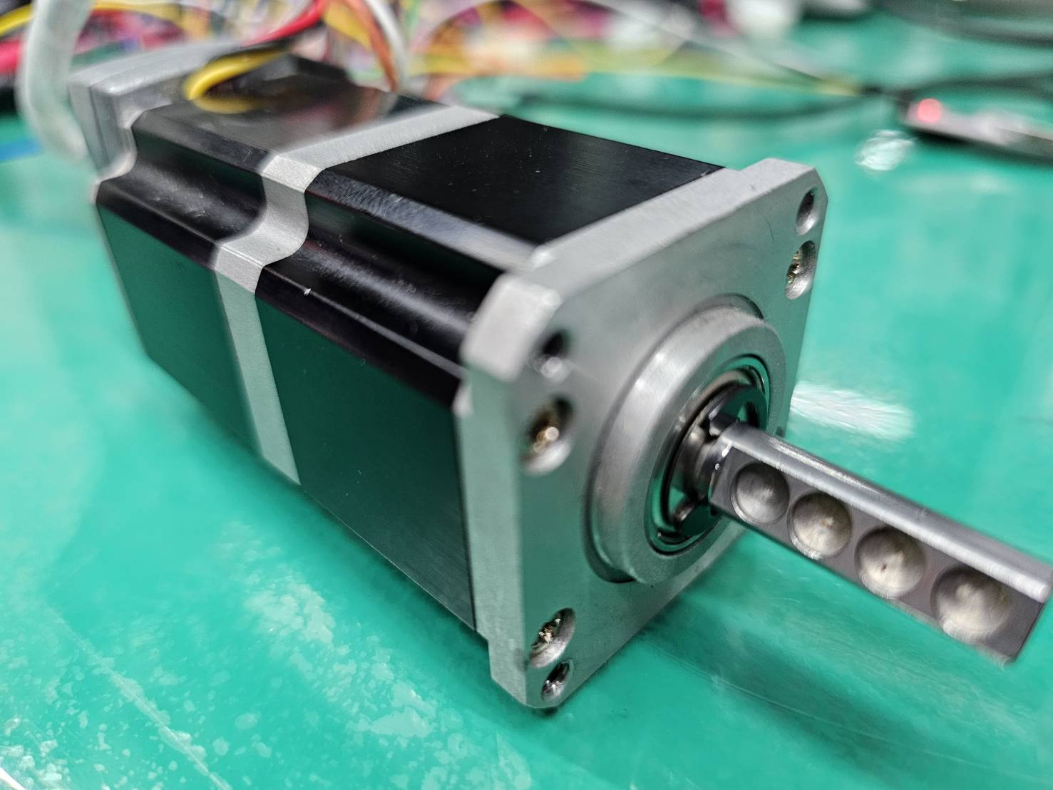
本篇所測試的馬達是瑞明系統科技有限公司的V2 直流無刷馬達,他是一顆直流無刷的馬達(廢話,他控制開迴路的速度非常簡單,主要有3條控制的線,一個是pwm控制速度,一個是ON/OFF,一個是正反轉控制,在控制開迴路時就根據這三條訊號線的控制就可以做到速度及正反控制。
馬達速度及正反轉開迴路控制
//-----------------------------------馬達參數更改自己的pin腳
const byte pwmPin = 32;
const byte FRPin = 33;
const byte onoffPin = 25;

void motorWrite(int power) {
  if (power == 0)
  {
    digitalWrite(onoffPin, 0);
    digitalWrite(FRPin, 0);
    analogWrite(pwmPin, power);
  }
  else if (power > 0)
  {
    digitalWrite(onoffPin, 1);
    digitalWrite(FRPin, 1);
    analogWrite(pwmPin, power);
  }
  else if (power < 0)
  {
    digitalWrite(onoffPin, 1);
    digitalWrite(FRPin, 0);
    analogWrite(pwmPin, -power);
  }
}

void setup() {

}

void loop() {
    motorWrite(100);
    delay(1000);
    motorWrite(20);
    delay(1000);
    motorWrite(0);
    delay(1000);
    motorWrite(-20);
    delay(1000);
    motorWrite(-100);
    delay(1000);
    motorWrite(0);
    delay(1000);
}
先寫一個副程式是有關於控制馬達速度,可以看到設定參數有power,就是設定馬達的速度大小,如果是設定正的話就是正轉,負的話就反轉,如果等於0的話就停止轉動,在loop中可以測試是否有控制正反及速度,如果是其他馬達的控制,比如說用L298n來驅動馬達的話,可以依造他的控制方式設計一個副程式,一樣設計一個變數power就可以控制馬達正反轉及速度。
馬達閉迴路PID位置控制
#define P_Position 1
#define I_Position 0.000
#define D_Position 0

#define LED 2
#define BOOT 0

// 在全局范围定义互斥锁
SemaphoreHandle_t xMutex;

TaskHandle_t Task1;

//-----------------------------------編碼器參數
const byte encoderPinA = 26;
const byte encoderPinB = 27;
const byte encoderPinZ = 14;

const int resolution = 100;

volatile int count = 0;
volatile int rev = 1;
volatile int preRev = 1;
volatile bool ZFlage = false;

int protectedCount = 0;
int previousCount = 0;
int shareCount = 0;
int getCount = 0;
int preCount = 0;

byte x = 0;

//-----------------------------------馬達參數
const byte pwmPin = 32;
const byte FRPin = 33;
const byte onoffPin = 25;

//-----------------------------------控制器參數

long angleError = 0;
long realAngle = 0;
long preAngle = 0;
long angleSpeed = 0;

long encoderLong = 0;
long realEncoder = 0;

long setCount = 0;

//Encoder
float errorEncoder = 0;
float preErrorEncoder = 0;
float preIEncoder = 0;
float PIDEncoder = 0;
float PID_pEncoder = 0, PID_iEncoder = 0,  PID_dEncoder = 0, prePIDEncoder = 0;

float motorSpeed = 0;
float preMotorSpeed = 0;

long millisTimer = 0;

void setup() {
  // put your setup code here, to run once:
  Serial.begin(115200);

  Serial.print("Task1 running on core ");
  Serial.println(xPortGetCoreID());

  pinMode(LED, OUTPUT);
  pinMode(BOOT, INPUT_PULLUP);

  pinMode(pwmPin, OUTPUT);
  pinMode(FRPin, OUTPUT);
  pinMode(onoffPin, OUTPUT);

  pinMode(encoderPinA, INPUT_PULLUP);
  pinMode(encoderPinB, INPUT_PULLUP);
  pinMode(encoderPinZ, INPUT_PULLUP);

  attachInterrupt(digitalPinToInterrupt(encoderPinA), isrA, CHANGE);
  attachInterrupt(digitalPinToInterrupt(encoderPinB), isrB, CHANGE);
  attachInterrupt(digitalPinToInterrupt(encoderPinZ), isrZ, RISING);

  digitalWrite(LED, LOW);

  // 初始化互斥锁
  xMutex = xSemaphoreCreateMutex();

  xTaskCreatePinnedToCore(
    Task1code,   /* Task function. */
    "Task1",     /* name of task. */
    10000,       /* Stack size of task */
    NULL,        /* parameter of the task */
    1,           /* priority of the task */
    &Task1,      /* Task handle to keep track of created task */
    0);          /* pin task to core 0 */
  delay(500);

  millisTimer = millis();
  ZFlage = false;
}

void motorWrite(int power) {
  if (power == 0)
  {
    digitalWrite(onoffPin, 0);
    digitalWrite(FRPin, 0);
    analogWrite(pwmPin, power);
  }
  else if (power > 0)
  {
    digitalWrite(onoffPin, 1);
    digitalWrite(FRPin, 1);
    analogWrite(pwmPin, power);
  }
  else if (power < 0)
  {
    digitalWrite(onoffPin, 1);
    digitalWrite(FRPin, 0);
    analogWrite(pwmPin, -power);
  }
}

void Task1code( void * pvParameters ) {
  int safeReading = 0;
  Serial.print("Task1 running on core ");
  Serial.println(xPortGetCoreID());

  Serial.println("等待按鈕");

  Serial.print("realEncoder:");
  Serial.println(0);

  while (1)
  {
    if (digitalRead(BOOT) == 0)
    {
      break;
    }
    delay(1);
  }

  while (1)
  {
    if (digitalRead(BOOT) == 1)
    {
      break;
    }
    delay(1);
  }

  Serial.println("初始化完畢");

  while (1) {
    if (millis() - millisTimer >= 5) {
      //讀取編碼器
      if (xSemaphoreTake(xMutex, portMAX_DELAY)) {
        // 存取共享資源...
        getCount = shareCount;
        xSemaphoreGive(xMutex); // 釋放互斥鎖
      }
      realEncoder = getCount - setCount;

      motorSpeed = getCount - preCount;

      //------------------------------------------------------PIDPosition
      errorEncoder = (14400 - realEncoder);

      PID_pEncoder = errorEncoder * P_Position;
      PID_iEncoder += errorEncoder * I_Position;
      PID_dEncoder = (errorEncoder - preErrorEncoder) * D_Position;

      PIDEncoder = PID_pEncoder + PID_iEncoder + PID_dEncoder;

      if (PID_iEncoder > 500)
        PID_iEncoder = 500;
      else if (PID_iEncoder < -500)
        PID_iEncoder = -500;

      if (PIDEncoder > 2048)
        PIDEncoder = 2048;
      else if (PIDEncoder < -2048)
        PIDEncoder = -2048;

      //------------------------------------------------------PIDPosition

      PIDEncoder = rpmMap(PIDEncoder);

      motorWrite(PIDEncoder);

      Serial.print("realEncoder:");
      Serial.println(realEncoder);

      preErrorEncoder = errorEncoder;
      preCount = getCount;

      millisTimer = millis();
    }
    vTaskDelay(pdMS_TO_TICKS(1));
  }
}

void loop() {
  // put your main code here, to run repeatedly:
  noInterrupts();

  if (ZFlage)
  {
    if (count < resolution / 2 && count > -resolution / 2)
    {
      count = 0;
    }
    else
    {
      if (count % (resolution * 4) > resolution / 2)
      {
        if (count < 0)
        {
          count = count - ((resolution * 4) + count % (resolution * 4));
        }
        else
        {
          count = count + ((resolution * 4) - count % (resolution * 4));
        }
      }
    }
    ZFlage = false;
  }

  protectedCount = count;

  interrupts();

  if (protectedCount != previousCount) {

    if (xSemaphoreTake(xMutex, portMAX_DELAY)) {
      // 存取共享資源...
      shareCount = protectedCount;
      xSemaphoreGive(xMutex); // 釋放互斥鎖
    }
    //Serial.println(protectedCount);

    if (x == 1)
    {
      digitalWrite(LED, HIGH);
    }
    else if (x == 0)
    {
      digitalWrite(LED, LOW);
    }

    if (x == 0)
      x = 1;
    else
      x = 0;
  }

  previousCount = protectedCount;
}

void isrA() {
  if (digitalRead(encoderPinA) != digitalRead(encoderPinB)) {
    count ++;
  } else {
    count --;
  }
}
void isrB() {
  if (digitalRead(encoderPinA) == digitalRead(encoderPinB)) {
    count ++;
  } else {
    count --;
  }
}
void isrZ() {
  ZFlage = true;
}

float rpmMap(float input) {
  return map(input, -2048, 2048, -255, 255);
}
以上為完整的PID位置控制的程式碼,其中只需要更改以下馬達的腳位就可以了,或是根據自己的馬達設計控制速度及正反轉的副程式。
//-----------------------------------編碼器參數
const byte encoderPinA = 26;
const byte encoderPinB = 27;
const byte encoderPinZ = 14;

const int resolution = 100;

//-----------------------------------馬達參數
const byte pwmPin = 32;
const byte FRPin = 33;
const byte onoffPin = 25;
接下來要調整所謂的PID參數。
#define P_Position 1
#define I_Position 0.000
#define D_Position 0
調整PID的參數都是從P開始去調試,其餘都設為0,一開始P設1,但其實一開始的P不一定是設1,以經驗法則來說P參數是比例參數,因此輸出的參數與Set Point及Process Variable參數的比例習習相關,我的習慣通常是,如果error的數值最大是100,馬達輸出最大是255,那麼我會設定P=2.55,當然這是符合大部分的情況下。
根據我的實際情況來說我的error最大,如果是以一圈來算的話,是14400的誤差,因為編碼器的PPR是100,而讀取編碼器的方法是讀取4次變化,則是4*100,而減速機的齒輪比是1:36,因此輸出軸轉一圈的話,編碼器會讀取到4*100*36=14400次訊號,如果是這樣設P為1的話,會讓一開始的error為最大值,輸出馬達就會是最大值,當誤差來到255時才會開始降速,不過每個系統又不太一樣,不同馬達輸出的曲線也不同,因此大家可以實際調過之後就能更了解PID的參數變化所帶來的影響,這裡就不太詳細介紹。
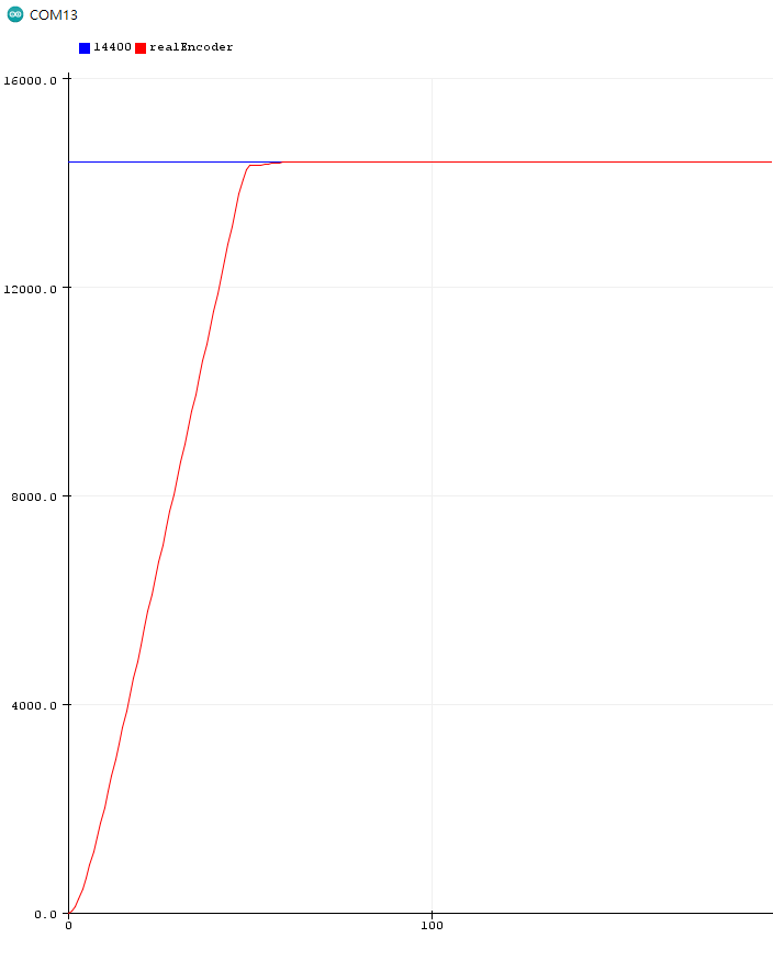
可以看到這是當P=2.5、I=0、D=5的時候馬達從0的位置跑到14400的地方的曲線。
以上就是PID位置控制的範例,其中內容可以改成其他不同馬達或編碼器,只要修改參數及馬達副程式即可。